
Home » Learn » Articles on Acoustics » Auralisation
“Auralisation”, also spelled as “auralization”, is the process of listening to any audio file as it would sound if played inside a simulated or measured space. For example, in ODEON it is possible to simulate how an orchestra, speech, or any other source would sound in the room you wish, at any position. The simulation results in a binaural audio, which is a highly realistic 3D sound or “out-of-head localization”, known as auralisation. The word “auralisation” is an analogy to the word “visualisation”, only referring to sound instead of visuals.
To get an early idea of what can be achieved via auralisation, try listening to the audio below which is a simulation of hand claps at different positions in an IEC listening room. Make sure to listen to it wearing headphones (the reason why this is required is explained further below).
In order to produce an auralisation, two main ingredients are required: a room’s measured or simulated impulse response, and an anechoic audio file. A room’s impulse response is a short signal that fully represents the room’s acoustics, containing information such as the frequency response and the reverberation time. However, a single impulse response is only valid for one source-receiver combination. You may read more about impulse responses in this page.
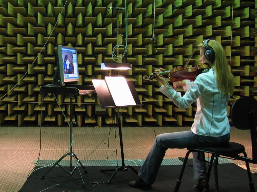
An audio file is “anechoic” when it has been recorded inside a fully absorbing chamber, therefore practically without any reflections (i.e.: in an anechoic chamber).
The reason why an auralisation requires an anechoic file is in order to avoid contaminating the auralisation with reflections from the recording room. Otherwise, the acoustics from two rooms would stack on top of each other: the target simulated/measured room (contained in the impulse response file) and the room where the recording was made (contained in the now not-so-anechoic audio file). In order to achieve an accurate auralisation, the only reflections involved in the process should be the ones contained in the impulse response.
In practice, an anechoic chamber can be difficult to find or to build. Therefore, a room with very low reverberation (called a dry room in acoustics) – such as a recording studio or a fully furnished and carpeted bedroom – can be a fair alternative.
An auralisation file is made by convolving the input anechoic audio file with the impulse response of the simulated or measured space. Convolution is a digital signal processing operation, which in simple words can be understood as a process that combines two time-varying signals in one.
The beauty of auralisation is that it makes it possible to listen to the same anechoic file as it would sound in different rooms, by combining it with the different impulse responses associated to those rooms.
In our website, you may find and freely download examples of anechoic files and impulse responses.
To create an auralisation, ODEON will first calculate the impulse responses between all desired sources, and a single listening position. Then, ODEON will convolve each impulse response with the anechoic audio associated to each impulse response. Finally, all resulting signals are added together.
The simplest way to experience an auralisation using ODEON is to create a binaural auralisation, meant to be reproduced over headphones.
However, for a binaural auralisation to be as realistic as possible, two additional facts must be considered: the interaction of sound with our bodies before it is picked up with our ears, and more importantly, the fact that humans typically listen with two ears. Accounting for these factors yields a more specific type of impulse response, called the “binaural room impulse response” (BRIR).
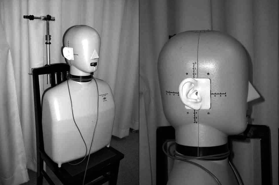
For creating the auralisations, a dummy head (having a microphone in the entrance of the left and right ear) is simulated in the receiver position. A real-life example of a dummy head is shown below.
This dummy head is simulated by introducing yet another step into the process: applying a head-related transfer function, or HRTF. This function is contained within a file which, when selected in ODEON, further modifies the impulse response to simulate the effects of:
This yields two new impulse responses, associated to the sound reception at each ear. Together, these two impulse responses constitute the binaural room impulse response. This file is applied on a single receiver, which means that despite being at a single position, it will produce two slightly different impulse responses.
It is important to consider that different people have slightly different bodies. Therefore, the only way to experience a practically perfect auralisation, is to obtain a measurement of your very own, personal head-related transfer function. However, this is very costly and complicated. In practice, one may simply use an average human HRTF, and this already produces a very realistic auralisation. Alternatively, you may download a public domain database of HRTFs for 45 different subjects, at this page.
For a faithfully simulated experience, auralisations are meant to be listened to using headphones, due to the following factors:
Moreover, one must remember that headphones also have their own impulse response, meaning that they will have a filtering effect on the electric signal. For an even more accurate auralisation, one could design a filter that compensates for the headphones’ response, allowing to play back the auralisation as intended. ODEON comes with a tool for designing headphone filters for binaural listening. For more details, you may consult Appendix D of the user manual.
An alternative way of producing an auralisation is via ambisonics. This is a full-sphere surround sound format, meaning that it is not restricted to a specific number of speakers, but instead it can be decoded for playback on any number of speakers regardless of the number of recording channels. So, any ambisonic recording can be decoded for e.g.: binaural or surround auralisation. Additionally, the listening orientation can be freely adjusted when decoding for binaural auralisation, whereas using a dummy head results in a fixed listening orientation.
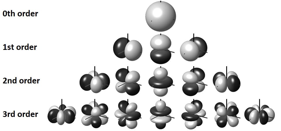
Ambisonics are based on the principle of spherical harmonics, which can be explained as a set of 3-dimensional orthogonal polar patterns that, when used together, can describe any 3D sound field with its direction characteristics.
Ambisonics aims to record a real or simulated impulse response using spherical harmonics up to a certain order, which would require a certain number of microphones depending on the desired ambisonic order. For Nth order ambisonics, at least (N+1)^2 microphones are required.
For example, 1st order ambisonics (the lowest possible order) would record an impulse response using 0th and 1st order spherical harmonics. The 0th order spherical harmonic would describe the omnidirectional sound, while the 1st order spherical harmonics describe the sound components in the x, y, and z directions. This corresponds to what would have been measured with one omnidirectional microphone and three perpendicular figure-of-8 microphones at the same position.
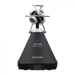
In practice, figure-of-8 microphones are considerably large in size for this application. Therefore, other configurations are used, for example, a set of 4 cardioid microphones in a tetrahedral arrangement, known as a “soundfield microphone”. An example of this type of probe is shown below.
The raw microphone recordings are referred to as A-format, which are not yet usable for ambisonics. Then, the A-format channels are processed to obtain directional information that corresponds to the spherical harmonics, resulting in a B-format signal. This is the standard format used for ambisonics.
For 1st order ambisonics, the B-format has 4 channels, named W, X, Y and Z. The omnidirectional information is stored in channel W, while the information in the x, y and z directions is stored in the X, Y and Z channels. This already gives us a 3D description of the sound field, although somewhat blurred. 2nd order ambisonics would use 0th, 1st and 2nd order spherical harmonics, for a finer description of the sound field. However, it would require a more complex probe with at least 9 microphones.
Impulse responses in 1st order ambisonics B-format can be simulated in ODEON, or loaded into the measurement system. Then, having loaded a B-format impulse response, you can adjust the listening orientation within ODEON for the auralisation.
ODEON can also decode a B-format impulse response for a 2D surround system (that is, a surround setup that does not involve the vertical direction). You would only need to specify your surround setup within the software before generating the impulse response. For any other speaker configuration, you can still get the impulse response in B-format, but you would need to decode it yourself outside of ODEON.
Several examples of binaural auralisation are available at this page. You will find auralisations of concert halls, worship spaces, among others. The auralisations are actually pretty fun to listen to, so we encourage you to check them out! For example, when listening to the receivers closest to and farthest from the source, the difference is very noticeable, especially in the level, and in the ratio between direct sound and reverberant sound.
In the case of concert halls, all listeners should ideally be able to not only see the orchestra playing, but also experience the sound with the same quality. However, in reality, concert halls are typically large rooms, so it is inevitable that the distance from the orchestra will vary considerably from position to position. Even the listening and viewing angle may differ. This is all taken into account when calculating the binaural room impulse responses to be convolved with the anechoic recordings for the final auralisation. Since the early reflections are not as strong for the listeners in the back of the hall in comparison with the ones close to the orchestra, it results in a more reverberant audio for listeners in the back in most of the cases.
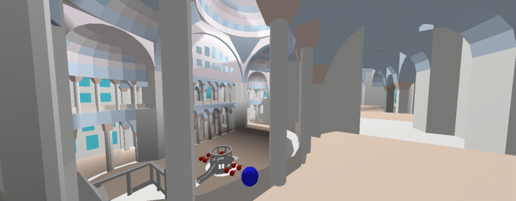
In the examples, pictures with a 3D view such as the one shown below are taken from ODEON’s 3D OpenGL, which is an alternative way of checking your room model and the sources and receivers’ positions. The red spheres are sources and the blue spheres are receivers.
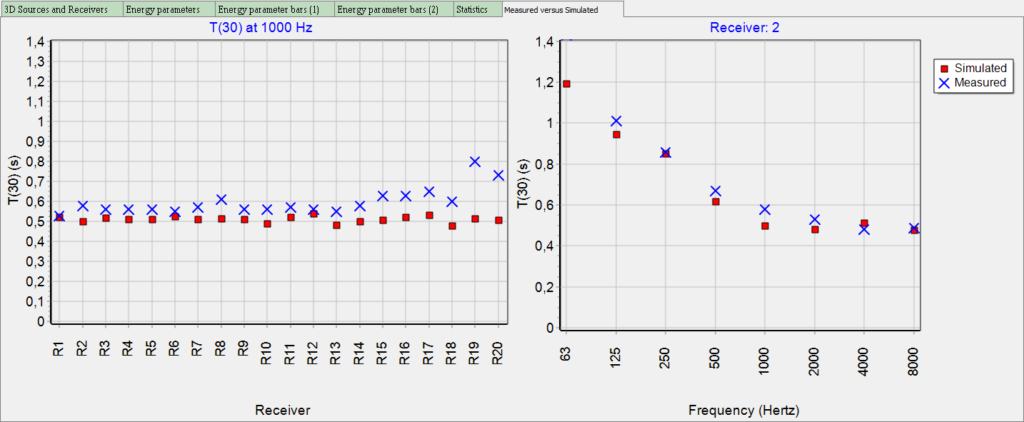
When simulating an existing place, it is usually difficult to have the information of the absorption coefficient of every surface in the room. A great idea to make sure your simulations are as real as possible, is to match the simulations to a measurement. The image below shows an example of one such comparison.
If you would like to make sure of the reliability of the software’s simulations, you can read up on room acoustic simulation round robins at this page.
You can get the impulse responses with a computer, ODEON 12 or newer, a source (omnidirectional), and a microphone (omnidirectional). You can learn about performing impulse response measurements by watching the videos at this page, or reading up in the user manual.
It is also possible to load the impulse response (.wav audio file) measured with any other device.
After running the multi-point calculation and comparing the measurement vs. simulation results, you should start tuning the model manually, trying different absorption and scattering coefficients in order to have less error. From ODEON 13, the genetic optimization tool is available, which is capable of tuning the model automatically for you.
Copyright © 2024 Odeon A/S
DTU Science Park, Diplomvej Bldg. 381
DK-2800 Kgs. Lyngby, Denmark
Tlf: +45 8870 8845
CVR No. DK 26391253
info@odeon.dk
Feel free to contact us for any question you may have! We will do our best to answer as soon as possible!
We can even set up a Skype demonstration before a potential purchase.
Would you like to receive important news regarding updates, courses etc. 3 – 5 times a year? Sign-up below!
Feel free to contact us for any question you may have! We will do our best to answer as soon as possible!
We can even set up a Skype demonstration before a potential purchase.
Please notice that you are contacting Odeon Room Acoustic Software company, which is not related to any other businesses that use the same name (Odeon cinemas, Odeon in Odense etc.).
Unfortunately we receive a lot of false inquiries lately. These will be deleted immediately in our account. Thank you for your understanding.
Please share your location to continue.
Check our help guide for more info.
